+- Like Ra's Naughty Forum (https://www.likera.com/forum/mybb)
+-- Forum: Self-Bondage (https://www.likera.com/forum/mybb/Forum-Self-Bondage)
+--- Forum: Self-Bondage Techniques (https://www.likera.com/forum/mybb/Forum-Self-Bondage-Techniques)
+--- Thread: DIY electromagnet based time-lock devices (/Thread-DIY-electromagnet-based-time-lock-devices)
Electrical engineer wanted - magnet cuffs idea - lovesagoodhogtie - 29 Mar 2024
Hi all,
I am looking for someone with arduino experience / electrical engineering experience. I want to make a magnet based self bondage cuff similar to the Magbound (https://selfbondage-shop.com/products/magbound-premium-self-bondage-time-14563) but without the wire. I tried a bit myself, but I am not well versed in hardware (I am a professional software developer though).
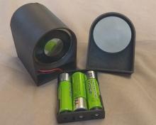
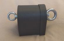
The idea is simple, take a magbound, remove the wire and replace it with a battery pack and an Arduino. As such, you have a very small mobile device which you can use for any sort of bondage. Using a battery, similar to the Magbound, allows automatic release when the batteries run out.
To add some fun, I thought about adding a mini arduino inside the 3d-printed housing to allow remote control. This arduino could be used to power-up and power-down the magnet using bluetooth, wifi, or a built-in timer.
I saw a similar idea on etsy once, but I can't find it anymore. I downloaded the images though:


Is there any electrical engineer / arduino expert who can help me with the electrical schematics? Maybe we could co-produce a test version?
I have no intention of selling this. Rather, I would like to make the final design open source for anyone to assemble.
Let me know if there is interest / help.
RE: Electrical engineer wanted - magnet cuffs idea - egregious - 29 Mar 2024
If you are a software developer there is no reason you can't do all this yourself.
Arduinos are programmed in a variety of C.
If you are only looking to power the magnet for a fixed time, you can get super low power tiny at (Arduino type system on a chip) boards from Ali express & a relay module that you connect it to to power the electromagnet.
Have you played with an Arduino before even if you just look at switch settings an turn LEDs on/off.
Bigger challenge will probably be that if the magnet is 12v and the Arduino is 5v, you'll need to solder up a 5v regulator. Then you have to work out what power the electomagnet takes & what size batteries will be needed, how to add a charging socket & what sort of charger do you need.
RE: Electrical engineer wanted - magnet cuffs idea - Tinker D - 29 Mar 2024
The digital safe lock could be used an example. The whole lock is powered by 3 or 4 AAA batteries. If your good at software engineering, you could build a lock/release system in a day or two.
RE: Electrical engineer wanted - magnet cuffs idea - Like Ra - 29 Mar 2024
It should not be Arduino:
https://s.click.aliexpress.com/e/_DkGdHxR
https://s.click.aliexpress.com/e/_Dl8qyhJ
https://s.click.aliexpress.com/e/_DlvqEfF
https://s.click.aliexpress.com/e/_DElwOu9 - this one is for Arduino
RE: Electrical engineer wanted - magnet cuffs idea - egregious - 30 Mar 2024
If it is 12v, and you just want a simple timer, you could just get a timer module Just found this amazing item on AliExpress. Check it out!
12V LED Display Countdown Ti timer relay board
RE: Electrical engineer wanted - magnet cuffs idea - Lancer - 30 Mar 2024
The magbound usually runs on 12volt inputs at standard usb power output. A buck converter that takes a managed power bank supply to power the magbound would work fine and be much more reusable than batteries.
As for controls all you need is a controller of choice (literally any with output pins, even the very commonly supported Pi zero would probably work), you would also need a mosfet of choice. Split the output of the USB with one set of wires going to power the controller and one set being interrupted by the mosfet that goes to the 12 volt converter for the magnet. The controller siphons a small amount of power from the power bank to power itself which gives you your interface and controls, the controller can activate the mosfet to allow the power bank to activate the magnet. I am skipping some electronics things with resistors but not by much.
RE: Electrical engineer wanted - magnet cuffs idea - Max515 - 30 Mar 2024
I did some MCU programming. Arduino doesn't have BT or wifi by itself. If you really want Arduino, an IR remote might work on GPIO pins.
There are BT/Wifi modules for Arduino, but those have an ESP inside. Why have two MCUs? Just use an ESP directly. You could even install Tasmota or ESPHome on it to control the relay with a very easy to use web interface, automations, integration with Home Assistant, etc.
You need a large battery for the magnet. Compared to that, power use from the MCU is extremely low, even if it's not programmed with power management in mind.
RE: Electrical engineer wanted - magnet cuffs idea - Tinker D - 30 Mar 2024
I thought the USB port is 5 volts. At least that’s what my volt-ohm meter says.
Now, the 4-Pin connector from the power supply of my pc, has +5 and +12 along with two commons or ground lines.
RE: Electrical engineer wanted - magnet cuffs idea - lovesagoodhogtie - 30 Mar 2024
hi all, thanks for all the replies!
I like Ra's idea of using a simple chip device as a relay. It is certainly the cheapest. The downside is that you can't program them. My idea was that as soon as it becomes software it becomes easy. Also, I was thinking of adding a load cell to one end of the magnet (can't find a cheap one now, something like this: https://s.click.aliexpress.com/e/_DmrChTr ). The idea would be to program it such that if you pull while the timer has not run out, it adds a few minutes.
This was also a very useful piece of information from Lancer: "As for controls ... need a mosfet of choice. ... ". Any chance you could draw me a schematic?
The magbound is indeed on 12v, 11watt (disassembled one, it appeared to be this one: https://s.click.aliexpress.com/e/_Dk0f9qH ). USB port is indeed 5 volt. This means that the holding force will be less than at 12v. Instead of 60kg, somewhere around 30, on top of my head. I saw a graph somewhere online (can't seem to find it now).
As controller I did some research. This one seems nice: https://esp32s3.com/tinys3.html . Small, and built in wifi and bluetooth. 😊
RE: Electrical engineer wanted - magnet cuffs idea - no smile - 01 Apr 2024
Well, you’ll in fact only need a resistor and a power mosfet or Darlington transistor.
If you take a transistor that is too short on the current it can take versus the current needed, you’ll also need to add a heat sink. But if you take one like 10x superior, you should be OK.
I would go for a tip1020g or o2n6045g like transistor, maybe with a small aluminium sheath as heat sink, but it’s probably not necessary. And drive it with a 1k resistor.
The circuit should be like :
Output pin -> resistor -> base pin of the transistor (check on the data sheet of the chosen one)
Emitter pin of the transistor -> GND
Magnet power voltage -> magnet, then magnet -> collector pin of the transistor.
Furthermore, you could use a volt gare regulator to use the same power supply and lower the 12v of the magnet power supply 5v needed by your esp board. Something like LM7805 is easy to find and use. You’ll find a practical use schematic on the data sheet of them.
Good luck 😉